Detector Construction
Detector Technology
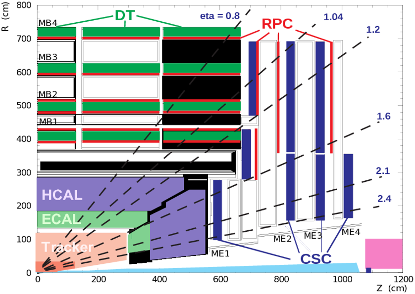
Types of technologies employed at CMS experiment to identify muons throughout the sub detector are generally referred to as "Muon Chambers".
Following are the 3 types of detectors installed in Muon Chambers.
-
Drift Tubes (DT)
-
Cathode Strip Chambers (CSC)
-
Resistive Plate Chamber (RPC)
Recently CMS introduced another type to the combination referred to as "GEM" detectors.
GEM = Gas Electron Multiplier
GE1/1 is a project aimed on a new technology of gaseous detector for muon tracking and expected to be added to the CMS End Caps during the long shutdown of the LHC between 2018 and 2020. Hence the GE1/1 project is in fact responsible for GEM implementation.
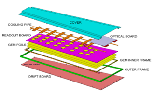
GEM Unit Construction
The construction of a single GEM detector with regard to the structural presentation and the presentation of such units in the Muon Chambers can be summerized as follows.
-
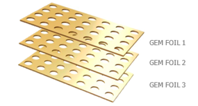
Basic components of GEM are constructed with 3 layers of GEM foils referred to as "triple GEM".
-
Foils in a Chamber have 2 sides distinguished as 'Top' and 'Bottom' but the solid copper boards have only one such defined side.
The GEM foils are,
- Tightly trapped between solid layers of copper boards.
- All boards are encapsulated inside a steel case.
- Case is filled with Ar and CO2 gases to acts as a Faraday chamber.
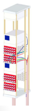
In addition to detecting technologies, a cooling system is implemented in Chambers to avoid overheating by employing a cooling pipe.
A Chamber is one such completed detector division.
-
There are a series of Chambers connected together to form the overall GEM detector.
-
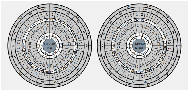
Refer the image representing the alignment of Chambers in End Caps as depicted in the GEM DCS.
-
The power supplies required by adapted technologies are different and specifically designed to facilitate muon detection.
Detector Process
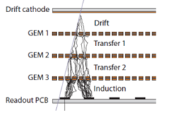
- When a muon passes through the detector, the particle ionizes the gas and creates electrons.
- GEM foils amplify the detection signal employing the general construction of Chambers.
- It accelerates the electron and the holes designed on surfaces of foils resulting an avalanche out of the particle.
The triplicating of this particular ionizing and multiplying electrons to provoke an avalanche assures a high efficiency of muon detection as the process ensures a definite readout at the end point of data acquisition.
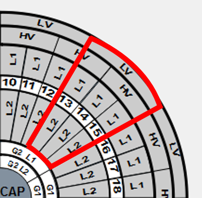
Detector Layout
The image below is a representative section of the GEM detector layout. Sections such as this will be covering a range of 360⁰ at each End Cap of the CMS detector.
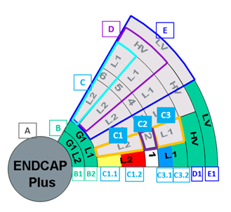
A : End Cap (Plus / Minus)
Indicate the End Cap name as ‘Plus’ or ‘Minus’ which each disc is associated with.
B : Gas Channel
Gas Channel indicates the gas status of a Chamber and the background color of the region changes according to the status at a given time. Each Gas Channel is connected to 6 Chambers.
One channel is connected to Top Chambers of 6 Super Chambers and another channel is connected to Bottom Chambers of same Super Chambers.
B1 : Gas Channel Status Bottom Layer Chambers (L1)
Indicates the Gas Channel status connected to Top Chambers of 6 Super Chambers.
B2 : Gas Channel Status of Top Layer Chambers (L2)
Indicates the Gas Channel status connected to Bottom Chambers of 6 Super Chambers.
C : Super Chamber
Indicates a single Super Chamber constructed by fixing 2 Chambers on each other. The 2 Chambers that design the Super Chamber are referred to as Top Layer Chamber (L1) and the Bottom Layer Chamber (L2).
C1 : Top Layer Chamber (L1)
C1.1 : High Voltage Status of Bottom Layer Chamber (L2)
Indicates the High Voltage Status (HV) of the bottom layer chamber
C1.2 : Low Voltage Status of Bottom Layer Chamber (L2)
Indicates the Low Voltage Status (LV) of the bottom layer chamber
C2 : Super Chamber Number
Indicates the Super Chamber number.
C3 : Bottom Layer Chamber (L2)
C3.1 : High Voltage Status of Top Layer Chamber (L1)
Indicates the High Voltage Status (LV) of the Top Layer Chamber.
C3.2 : Low Voltage Status of Top Layer Chamber (L1)
Indicates the Low Voltage Status (LV) of the Top Layer Chamber.
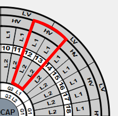
There are 36 Super Chambers per End Cap therefore 72 Super Chambers and 144 Chambers in total are associated with the GEM detector at CMS.
Voltage Supplies
Foils in a Chamber have 2 sides distinguished as 'Top' and 'Bottom' but the solid copper boards have only one such defined side.
The +copper layer is referred to as the 'Drift Board' only has a Bottom side and the -copper layer a Top side. Drift Board and all layers in foils require a high voltage for performance while the -copper layer is grounded.
High voltages are given to 7 defined sides per Chamber while a single Chamber only requires 1 low voltage input.
High Voltage Supply
D : High Voltage Board
Indicates the High Voltage Board that facilitates the high voltage power supply and the background color of a region changes according to the status.
D1 : High Voltage Board Status
Indicates the High Voltage Board status.
HV Board indicates the HV supply via a single power supply that distributes voltages to 2 Super Chambers. 7 channels from the power supply cover the layers L1 and L2 of a Super Chamber whilst the other 7 cover the other Super Chamber indicated in the HV Board.
HV Power Supply Connection
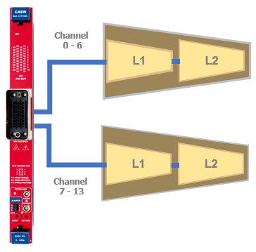
HV power supply has 14 channels therefore a single HV power supply is connected to 2 Chambers to cover the required HV inputs. But the detector is designed in a way that one HV power supply would facilitate the power requirement for 2 Super Chambers.
HV Distribution in Disc View
Low Voltage Supply
E : Low Voltage Board
Indicates the Low Voltage Board and the background color of a region changes according to the status.
E1 : Low Voltage Board Status
Indicates the Low Voltage Board status.
LV power supply has 6 channels therefore a single LV power supply is connected to 6 Chambers to cover the required LV input.
LV Power Supply Connection
LV Board indicates 3 Super Chambers (i.e. 6 Chambers) that are being covered by the same LV supply.
LV Distribution in Disc View
Power System and Distribution
CAEN Modules and Connections
For any detector associated with CERN experiments, voltage controlling happens via a DCS as they are all placed underground.
Even underground power supplies and detectors are connected through a series of structures that are in communication with controlling systems.
Main Frame is the structure stationed underground such that the DCS could communicate thus controlling voltage levels to provide power supplies in order to dispense power according to their specific requirements.
Direct communication from user machines to Main Frames is not possible. In order to achieve the possibility, a middle application referred to as OPC Server is employed.
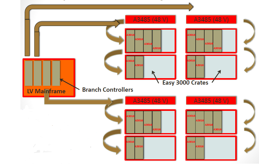
Underground structures are connected together as presented below employing a series of CAEN modified structures.
Main Frame
All HV and LV power supplies are connected to Main Frames directly or indirectly.
Voltage supply to the Main Frame is in a high range and not possible to achieve low voltage states without external structures.
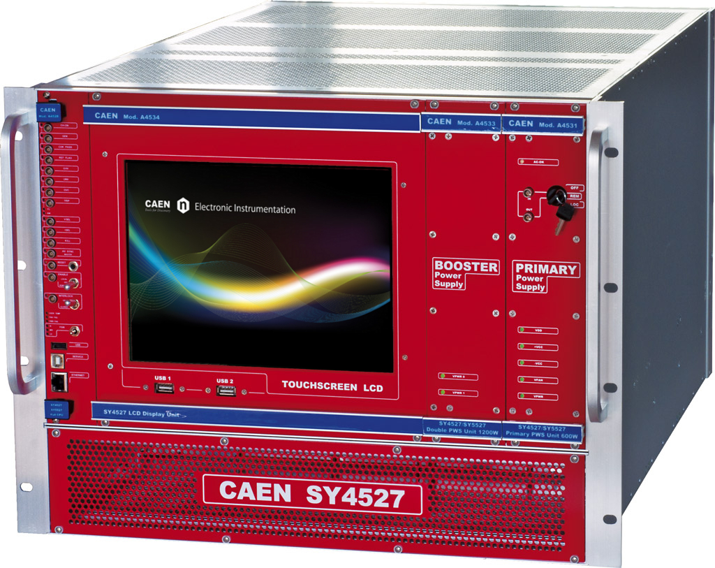
Figure : CAEN SY4527 Main Frame
HV Power Supply Board
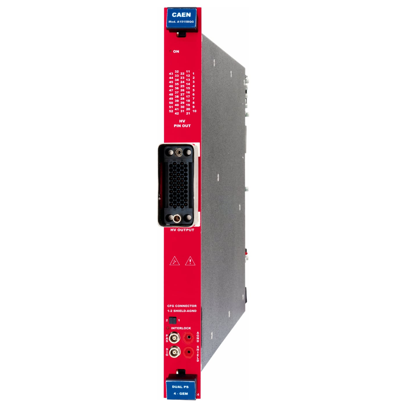
A1515 HV power supplies are directly connected to the Main Frame.
It is possible to connect HV power supplies to the Main Frame via the 16 available ports.
Figure : A1515 HV Power Supply Board
Branch Controller
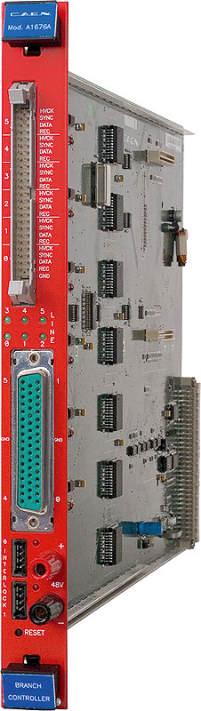
Branch Controller structure is connected directly to the LV Main Frame.
Multiple Branch Controllers can be connected to the Main Frame based on the required number of Easy Crates.
Figure : A1676A Easy Branch Controller
Easy Crate
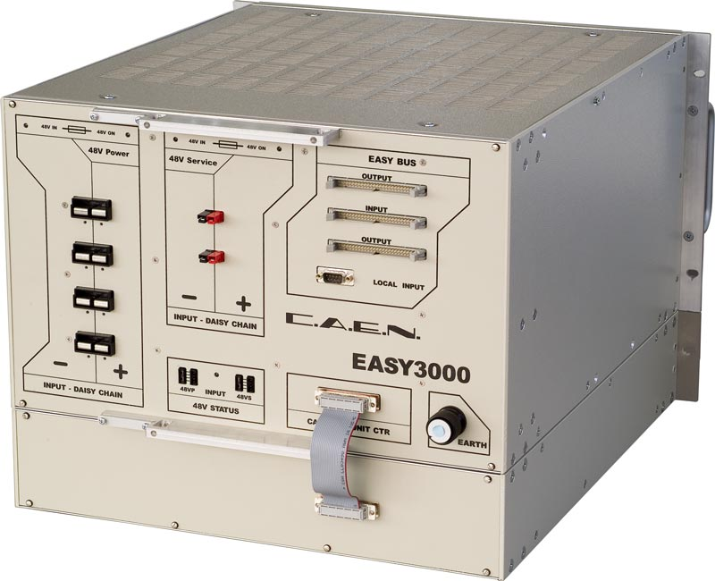
Easy Crates are directly connected to a Branch Controller.
X Easy Crates can be connected to 1 Branch Controller as many Easy Crates are employed to facilitate 24 LV power supplies.
Figure : EASY3000 Easy Crate
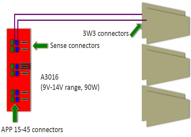
LV Power Supply Board
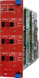
A3016 LV power supplies are connected to Easy Crates.
Only 5 LV power supplies can be connected to 1 Easy Crate hence multiple Easy Crates are employed to facilitate the 24 LV power supplies required by GEM.
Figure : A3016 LV Power Supply Board
Overall LV power supply boards to LV Main Frame connections through middle modules can be summarized as below employing all involved CAEN structures.
LV power supplies are not connected to the Main Frame directly as obtaining the required voltage of 48V is not possible therefore a separate power supply (MAO) is connected.
GEM Power Distribution
There are 2 racks assigned for each End Cap powering detectors in one half of the End Cap. Those racks are placed on one of the stages designed at CMS End Cap on each side.
Racks are the structures designed to place CAEN modules and all required power supplies that are employed to power the GEM detector system. Each rack hosts 2 CAEN Main Frames,
Rack 1 : Main Frame for HV power supplies
Rack 2 : Main Frame for LV power supplies
The GEM detector power system is distributed into 2 sections for each End Cap.
One such section is identified as the ‘Far Side’ while the other side is identified as the ‘Near Side’.
The division of sections was done based on Super Chambers and the Super Chamber numbers in each section are as follows.
1. HV Sections Division Mapping
Near side Super Chamber numbers :
28/29 , 30/31 , 32/33 , 34/35 , 36/1 , ⅔ , ⅘ , 6/7 , 8/9
Far side Super Chamber numbers :
10/11 , 12/13 , 14/15 , 16/17 , 18/19, 20/21 , 22/23 , 24/25 , 26/27
Coupling of Super Chambers in ‘far side’ and ‘near side’ is based upon the fact that HV power supply boards facilitate 2 Super Chambers.
2. LV Section Division Mapping
Near side Super Chamber numbers :
19/20 , 21/22 , 23/24 , 25/26 , 27/28 , 29/30 , 31/32 , 33/34 , 35/36
Far side Super Chamber numbers :
½ , 3/ 4 , ⅚ , ⅞ , 9/10 , 11/12 , 13/14 , 15/16 , 17/18