General Guide for Buttons on Main Interface
All the guides considered in this category are accessible via buttons on the Main interface. It should be noted that some of the buttons in this part might have restrictions depending on the privilege type.
In order to access the 'Recipe' mode and the 'DAQ Commands' mode, expert privileges are required.
Kill Mode
A single click on this button will result in killing the system thereby terminating all processes that are in progress. The following dialog box will appear for the confirmation of the command.
Settings Mode
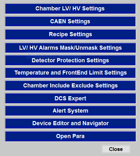
Only experts have the privilege to change most of the settings. A single click on the "Settings" button results on the panel below consisting of several settings options accessible to general users and experts.
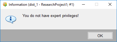
If the selected setting type requires expert privileges and the user does not have expert privileges the following dialog box will appear.
There are settings accessible for users without expert privileges. But in any case if the user do not know what to do precisely, it is recommended to seek expert advise.
Chamber Include/Exclude Settings
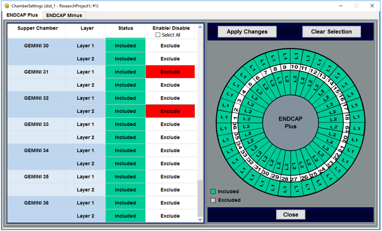
The "Chamber Include/Exclude Settings" option in the 'Settings' panel leads to the following panel which allows a user, the possibility of including or excluding of a selected Chamber.
The 2 tabs represent the 'End Cap Plus' and the 'End Cap Minus' both of which are exact in respective configurations.
Device Editor Navigator Panel Access
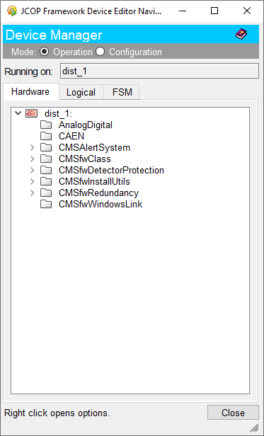
The 'Device Editor Navigator' panel can be accessed by clicking on the button with the same name in the 'Settings' panel. This panel is accessible but not necessarily useful unless the user is an expert or a developer.
Para Module Access
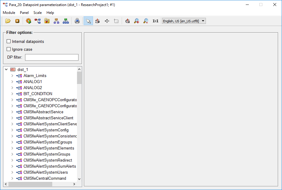
The 'Para Module' panel can be accessed by clicking on the "Open Para" button in the 'Settings' panel. This panel is accessible but not necessarily useful unless the user is an expert or a developer.
Alarm Screen
The 'Alarm Screen' allows the user to view, acknowledge, and filter alarms in the process of alarm handling. The user must always acknowledge and react to alarms which could be dangerous to the entire system otherwise.
The user can acknowledge alarms by clicking on the "Acknowledge" button on the alarm screen after selecting the recieved alarm notification(s).
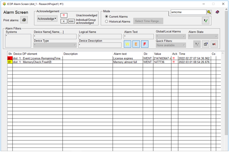
Alarm Information
- Level of the alarm (Warning, Error, Fatal)
- DPE and DPE value involved in the alarm
- Description and the text associated with the alarm
- Direction (Came / Went)
- Acknowledgment status
- Time Stamp
Alarm Notification System
- SMS is sent to the GEM DOC phone and a list of few experts
- Email is sent to the list cms-gem-dcs-notifications
- Alarm appears in the alarm screen
- Background color of the indicator changes color according to the error
Refer the “Reacting to Alarms” section before reacting to an alarm if unsure on appropriate actions with regard to alarm notifications.
SMS or email notifications would not be sent 2 times for a variable, if the 1st alert was not acknowledged!
Scan Panels
HV Scan Panel
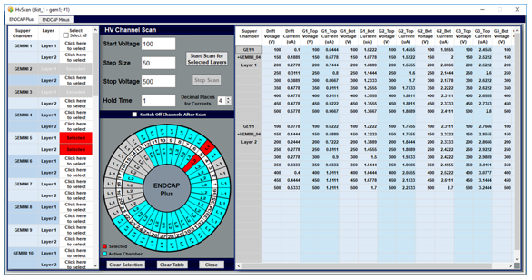
This panel is used to perform HV scans for selected Chambers. Selections made by the user will be highlighted in red color in both tabular and graphical representation of chambers.
The 2 tabs represent the ‘End Cap Plus’ and the ‘End Cap Minus’ both of which are exact in respective configurations.
LV Scan Panel
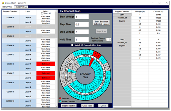
This panel is used to perform LV scans for selected Chambers. Selections made by the user will be highlighted in red color in both tabular and graphical representation of chambers.
The 2 tabs represent the ‘End Cap Plus’ and the ‘End Cap Minus’ both of which are exact in respective configurations.
Operating Scan Panels
Start HV or LV scanning process
- Select layers from the table for the scanning process.
- Include appropriate values into cells in the "HV Channel Scan" or "LV Channel Scan" section.
- If necessary check the "Switch off Channels After Scan".
- Click on "Start Scan for Selected Layers".
Internal Processing
- Selected layers will be highlighted in red in both tabular and graphical presentations.
- Scanning will start from the 'Start Voltage' and will be incremented by the 'Step Size' every instant satisfied by the 'Hold Time' until the voltage reaches the 'Stop Voltage'.
- If switched off layers will be colored in gray in the graphical presentation.
- If the 'Start Scan' was clicked then selected Chambers will be scanned one by one and results will appear in the table on the right side.
Purpose of Buttons
- Start Scan for Selected Layers : Start the scanning process
- Stop Scan : Abort the scanning process
- Clear Selection : Clear all selected Super Chambers
- Clear Table : Erase all scan results in the table
Power Cycle LV
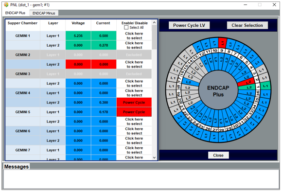
This panel is used to power cycle the LV for selected Chambers and the power cycling status for each Chamber will be displayed in the message area of the popup panel.
The 2 tabs represent the ‘End Cap Plus’ and the ‘End Cap Minus’ both of which are exact in respective configurations.
Power Cycle Process
- Select one or multiple Chambers from the "Enable/Disable" column.
- Click on the "Power Cycle LV" to start the power cycling process.
- Click on the "Clear Selection" button will clear all selected Chambers.
Internal Process
- All selected Chambers will be highlighted in red in both tabular and graphical representations.
- Single iteration of the power cycle will occur and status will be shown in the message area. Results of each selected layer will appear in the table on the right side.
Purpose of Buttons
- Power Cycle LV : Start the power cycling process
- Clear Selection : Clear all selected Super Chambers


