Status Interface
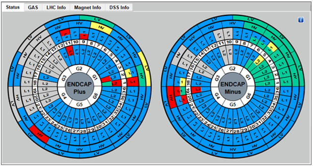
The ‘Status’ tab in the main interface of DCS provides an overview for the whole system i.e. HV and LV status, status monitoring etc.
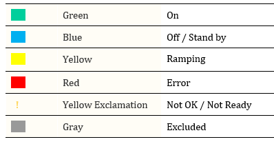
Color at a given time indicates the status of the selected section.
Color Code
Detector Status
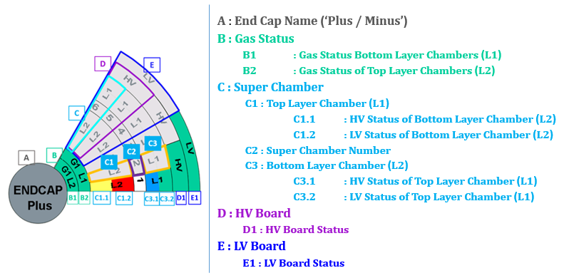
The circular disc regions indicate End Caps of the CMS detector and each disc is created with trapezoids. Trapezoids represent Chambers (complete GE1/1 detectors) and provide information on power supply boards and gas channels.
Representation
Refer "GEM Structural Delineation" for more information on power supply module board divisions and power supply connections.
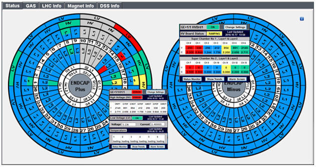
Each of the parts gas status chambers, super chambers, chambers associated with super chambers, HV boards and LV boards will present popup panels with further relevant information if you clicked on a section.
Chamber Status Panel
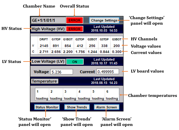
This popup panel displays the overall status of a single Chamber in a Super Chamber. Refer the image for the display of the Chamber Status popup panel.
Chamber status, HV status, LV status, voltage values and current values of GEM foils will be presented with the relevant color based on defined ranges for the status.
The buttons in the popup panel are designed for tasks given below.
Status Monitor Panel
This panel is used only for monitoring the status of HV and LV, thus users cannot perform any changes to HV and LV values on this panel.
This panel displays more information on the HV and LV status of a single Chamber and users can monitor the information easily in addition to moving to more panels.
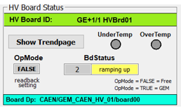
HV Board Status
Accessible Information
- HV Board ID and HV Board DP
- HV Board status
- Operating Mode
- Temperature status
Accessible panels
- Click on ‘Show Trends’ to access HV trends panel
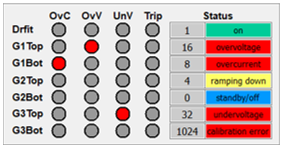
HV Channel Status
Accessible Information
- HV Channel status
- HV faulty states if exists
HV Values
Accessible Information
- Readback settings
- Actual HV channel values
LV Board Status
Accessible Information
- LV Board ID and DP
- LV Board status
Accessible Panels
- Click on ‘Show Trends’ to access LV trends panel
LV Channel Status
Accessible Information
- LV Channel status
- LV faulty states if exists
- Readback settings
- Actual LV Channel value
Users can get the DP name (path) of each HV and LV channel by hovering the mouse cursor on the GEM foil name (Drift, G1Top, G1Bot, etc. ).
HV and LV Channel statuses will be presented with the relevant status colors and codes. Refer 'Color Code' and status key in 'Representation' for definitions.
Change Settings Panel
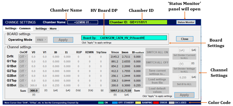
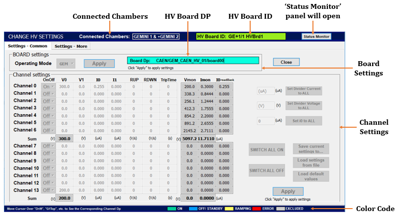
This panel is used to change HV settings of a single Chamber. Users with expert privileges are allowed to change necessary settings.
Only experts and operators have access to change the settings, others can only view.
The window has 2 tabs ‘Settings - Common’ and ‘Settings - More’. If the user clicked on the ‘Settings - Common’ tab below panel interface will appear.
Board Settings Applications
- Select the relevant "Operating Mode".
- If required, change HV Channel DP values connected to the Chamber.
- Click the "Apply" button and confirm the application.
Channel Settings Applications
- Switch off the channel that is expected to get modified.
- Click on the cell and select the current value where the change is required.
- Type and enter the new value in the cell (If more than 1 change is required type them all in relevant cells).
- Click the "Apply" button and switch on the channel.
Purpose of Buttons
- Switch All On : Switch on all the channels
- Switch All Off : Switch off all the channels
- Save Current Settings : Save current settings in a given destination
- Load Settings from File : Load settings from a selected directory
- Load Default Values : Load predefined default values
- Set Divider Current to All :
- Set Divider Voltage to All :
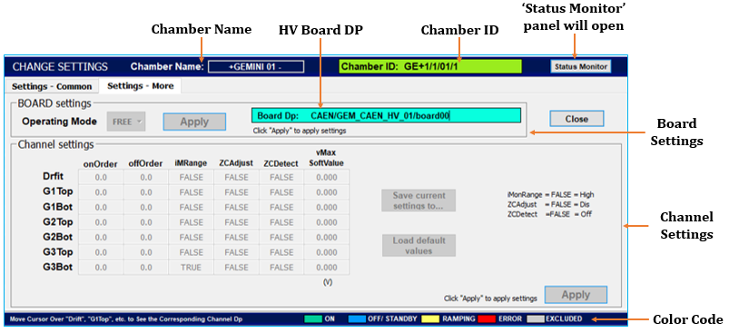
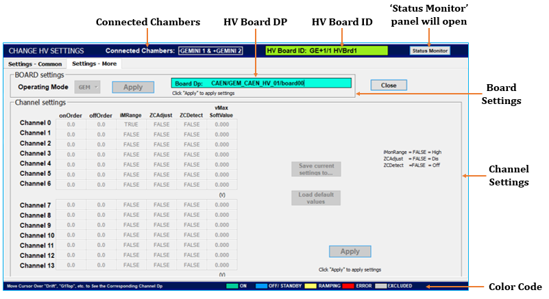
If the user clicked on the ‘Settings-More’ tab the resultant panel will be as follows.
Users can get the DP name (path) of each voltage channel by hovering the mouse cursor on the GEM foil name (Drift, G1Top, G1Bot, etc. ).
Show Trends Panel
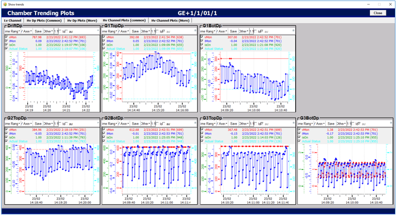
This panel is used to view trending plots of a selected Chamber.
Customizing Trending Plots
-
Time Range : The interval to plot can be selected by ticking on avaliable options in the list or via 'Specify a Time Range' option.
-
Y Axes : Zoom in and zoom out options are available for the user to apply as preferred.
-
Save : Provide a series of options to save trending plots.
-
Other : Many other options (i.e. X axes adjustments etc.).
-
Log / Auto Check Boxes : Presents the option to view plots in a log scale or a normal scale.
Support Probes
-
Legend : A color based legend automatically appears with a plot and user has the ability to remove a certain entry class by simply unchecking the relevant check box.
-
Reading Point Values : With a simple click on a data point in the plot pops a movable vertical cursor and a table presenting values along the vertical cursor.
-
Time Stamp : Along with each collected data point comes a time stamp and the X axis represents date and time.
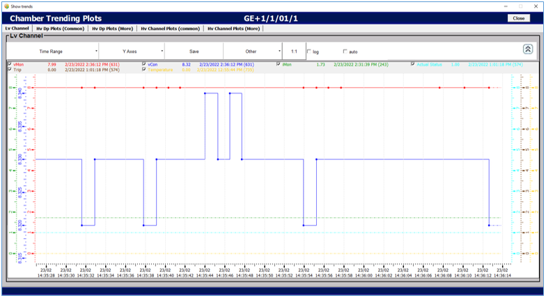
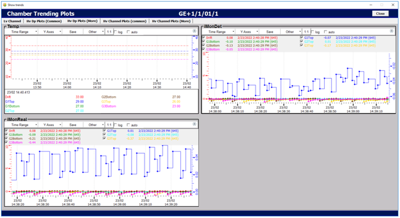
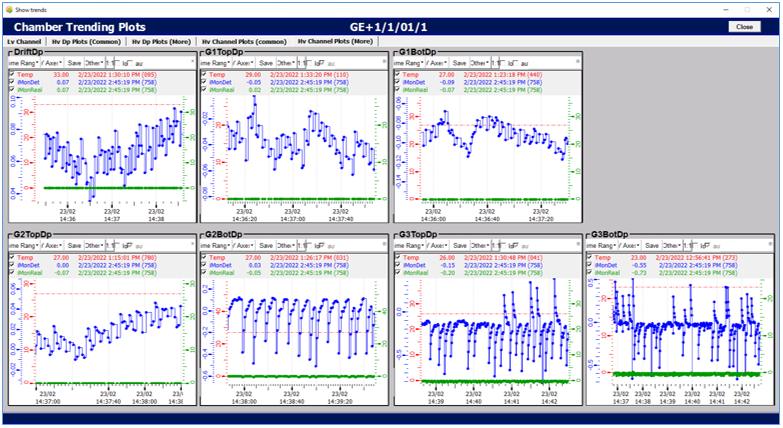
In the 'Chamber Trending Plots' panel there are 3 tabs each presenting trending plots for specific parts associated with HV system.
LV Channel
HV DP Plots (Common)
HV DP Plots (More)
HV Channel Plots (Common)
HV Channel Plots (More)
Alarm Screen Panel
This panel is used to open the alarm screen.
HV Board Status Panel
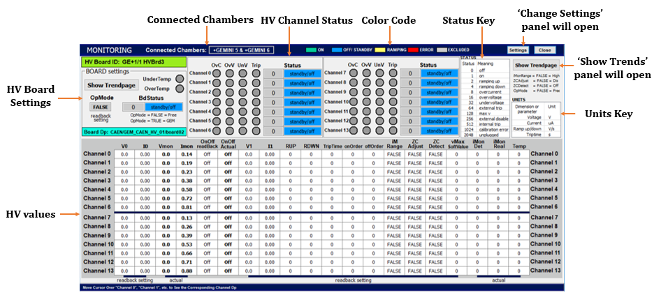
This popup panel displays the overall status of the High Voltage Board. It displays the HV Board name, on/off status of the Board, Board status, voltage and current values of all 14 channels of that HV Board and the Chamber names connected to this HV board.
HV status, voltage values and current values of each channel will be presented with the relevant color based on defined ranges for the status.
The buttons in the popup panel are designed for tasks given below.
Status Monitor Panel
This panel displays more details of the HV Board status and is used only for monitoring the status of a HV Board, thus users cannot perform any changes on HV values in this panel.
This panel displays more information on the HV and LV status of a single Chamber and users can monitor the information easily in addition to moving to more panels.
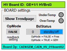
HV Settings
Accessible information
- HV Board ID
- Temperature status
- HV Board status
- Operating Mode
- HV Board DP
Accessible panels
- Click on ‘Show Trends’ to access HV trends panel
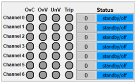
HV Channel Status
Accessible information
- HV Channel status for all 14 channels
- HV faulty states if exists
Similiar sub panel exists for the rest of the channels.
HV Values
Accessible Information
- Readback settings
- Actual HV Channel values
Users can get the DP name (path) of each HV and LV channel by hovering the mouse cursor on the GEM foil name (Drift, G1Top, G1Bot, etc. ).
Change Settings Panel
This panel can be used to change settings of HV Boards. Users with expert privileges are allowed to change necessary settings.
Only experts and operators have access to change the settings, others can only view.
The window has 2 tabs 'Settings - Common' and ‘Settings - More’. If the user clicked on the ‘Settings - Common’ tab below panel interface will appear.
Board Settings Application
- Select the relevant "Operating Mode".
- If required, change HV Channel DP values connected to the Chamber.
- Click the "Apply" button and confirm the application
Channel Settings Application
- Switch off the channel that is expected to get modified.
- Click on the cell and select the current value where the change is required.
- Type and enter the new value in the cell (If more than 1 change is required type them all in relevant cells).
- Click the "Apply" button and switch on the channel.
Purpose of Buttons
- Switch All On : Switch on all the channels
- Switch All Off : Switch off all the channels
- Save Current Settings : Save current settings in a given destination
- Load Settings from File : Load settings from a selected directory
- Load Default Values : Load predefined default values
- Set Divider Current to All :
- Set Divider Voltage to All :
- Set i0 to All : Update all i0 values with the value typed in cell
If the user clicked on the ‘Settings-More’ tab, the resultant panel will be as follows.
Users can get the DP name (path) of each voltage channel by hovering the mouse cursor on the GEM foil name (Drift, G1Top, G1Bot, etc. ).
Show Trends Panel
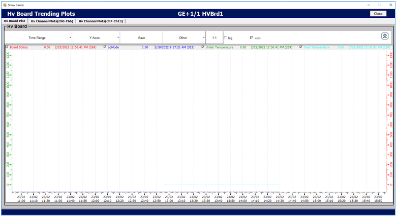
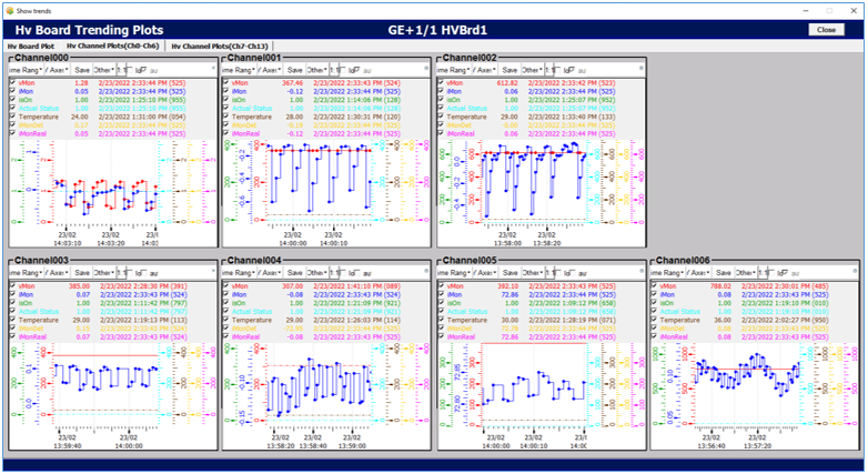
This panel is used to view trending plots of HV channels.
Customizing Trending Plots
-
Time Range : The interval to plot can be selected by ticking on avaliable options in the list or via 'Specify a Time Range' option.
-
Y Axes : Zoom in and zoom out options are available for the user to apply as preferred.
-
Save : Provide a series of options to save trending plots.
-
Other : Many other options (i.e. X axes adjustments etc.).
-
Log / Auto Check Boxes : Presents the option to view plots in a log scale or a normal scale.
Support Probes
-
Legend : A color based legend automatically appears with a plot and user has the ability to remove a certain entry class by simply unchecking the relevant check box.
-
Reading Point Values : With a simple click on a data point in the plot pops a movable vertical cursor and a table presenting values along the vertical cursor.
-
Time Stamp : Along with each collected data point comes a time stamp and the X axis represents date and time.
In the 'HV Board Trending Plots' panel there are 3 tabs each presenting trending plots for specific parts associated with HV system.
HV Board Plot
HV Channel Plots (Channels 0 - 6)
HV Channel Plots (Channels 7 - 13)
- Contents in these plots present trends for channels 7 through 13 similar to the presentation of channels 0 through 6.
Alarm Screen Panel
This panel is used to open the alarm screen.
LV Board Status Panel
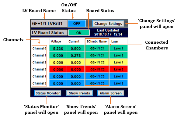
This popup panel displays the overall status of the Low Voltage Board. It displays the LV Board name, on/off status of the Board, Board status, voltage and current values of all 6 channels of that LV Board and the Chamber names which are connected to that LV board.
LV status, voltage values and current values of each channel will be presented with the relevant color based on defined ranges for the status.
The buttons in the popup panel are designed for tasks given below.
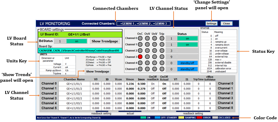
Status Monitor Panel
This panel displays the LV Board status and is used only for monitoring the status of a LV Board, thus users cannot perform any changes on LV values in this panel.
This panel displays more information on the LV status of a single Chamber and users can monitor the information easily in addition to moving to more panels.
LV Settings
Accessible information
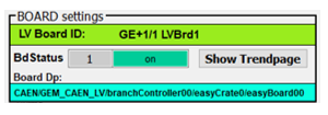
- LV Board ID and LV Board DP
- LV Board status
Accessible panels
- Click on ‘Show Trends’ to access LV trends panel
LV Channel Status
Accessible Information
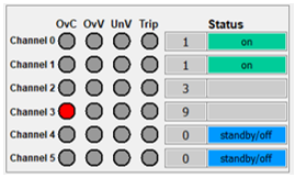
- LV Channel status for all 6 channels
- LV faulty states if exists
LV Values

Accessible Information
- Readback settings
- Actual LV Channel values
Users can get the DP name (path) of each LV channel by moving the mouse cursor on channel name (channel0, channel1, etc.).
Change Settings Panel
This panel can be used to change the LV settings of a LV board and this panel can be used to change settings of individual channels.
Only experts and operators have access to change the settings, others can only view.
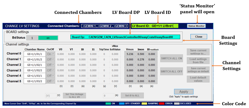
Board Settings Application
- Select the relevant "Operating Mode".
- If required, change LV Channel DP values connected to the Chamber.
- Click the "Apply" button and confirm the application.
Channel Settings Application
- Switch off the channel that is expected to get modified.
- Click on the cell and select the current value where the change is required.
- Type and enter the new value in the cell (If more than 1 change is required type them all in relevant cells).
- Click the "Apply" button and switch on the channel.
Purpose of Buttons
- Switch All On : Switch on all the channels
- Switch All Off : Switch off all the channels
- Save Current Settings : Save current settings in a given destination
- Load Settings from File : Load settings from a selected directory
- Load Default Values : Load predefined default values
- Set Divider Current to All :
- Set Divider Voltage to All :
- Set i0 to All : Update all i0 values with the value typed in cell
- Set v0 to All : Update all v0 values with the value typed in cell
Users can get the DP name (path) of each LV channel by hovering the mouse cursor on channel name (channel0, channel1, etc.).
Show Trends Panel
This panel is used to view trending plots of LV channels.
Customizing Trending Plots
-
Time Range : The interval to plot can be selected by ticking on avaliable options in the list or via 'Specify a Time Range' option.
-
Y Axes : Zoom in and zoom out options are available for the user to apply as preferred.
-
Save : Provide a series of options to save trending plots.
-
Other : Many other options (i.e. X axes adjustments etc.).
-
Log / Auto Check Boxes : Presents the option to view plots in a log scale or a normal scale.
Support Probes
-
Legend : A color based legend automatically appears with a plot and user has the ability to remove a certain entry class by simply unchecking the relevant check box.
-
Reading Point Values : With a simple click on a data point in the plot pops a movable vertical cursor and a table presenting values along the vertical cursor.
-
Time Stamp : Along with each collected data point comes a time stamp and the X axis represents date and time.
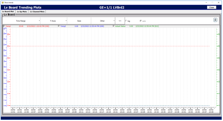
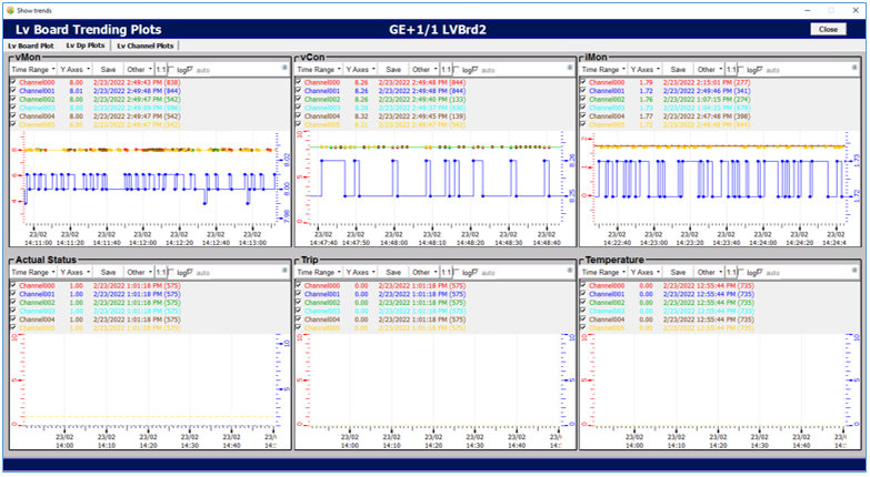
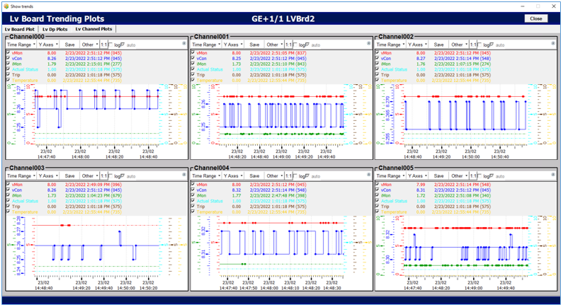
In the 'LV Board Trending Plots' panel there are 3 tabs each presenting trending plots for specific parts associated with LV system.
LV Board Plot
LV DP Plots
LV Channel Plots
Alarm Screen Panel
This panel is used to open the alarm screen.
Gas (Flow Cell) Status Panel

Gas status popup panel displays the flow cell name, on/off status, relevant layer, the inflow of gas and the outflow of gas. In addition there are a few buttons designed for tasks given below.
Show Trends Panel
This panel is used to view trending plots of Flow Cells.
Alarm Screen Panel
This panel is used to open the alarm screen.
